What is the Process Scheme section?
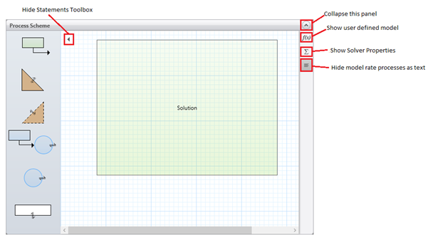
The Process Scheme is a picture that shows all the phases and rate processes that are currently included in your model. Here is the default process scheme, showing a single liquid phase called Solution, where the display of any reactions text has been hidden (or before any reactions have been defined).
Statements toolbox
Click on the process scheme icon ( ) to show the "statements toolbox". To hide the toolbox again, click on the
  icon.
icon.
Using the statements toolbox, you can add elements to your model. Below is a description of the different phase types available in the toolbox:
|
|
Meaning
|
Description
|
|
|
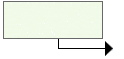
Miscible Liquid Feed
|
Feeds a fully miscible liquid from a Feed Tank to the Solution phase
|
|

|
Dissolving Solid
|
Adds a solid that dissolves in the Solution phase
|
|

|
Precipitating Solid
|
Adds a solid phase that precipitates out of the Solution phase after the solubility of a product is exceeded.
|
|
|
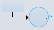
Immiscible Liquid Feed
|
Feeds an immiscible liquid from a Feed Tank to an immiscible liquid phase. If an immiscible liquid phase is already present in the reactor vessel, this will connect the feed to that phase, otherwise it will create a new phase.
|
|

|
Immiscible Liquid
|
Adds an immiscible liquid phase
|
|

|
Gas Phase
|
Adds a headspace containing gas
|
Miscible Liquid Feed
Double clicking on the Miscible Liquid Feed in the toolbox will bring up the following window, where we have already added Reagent to the list of materials.
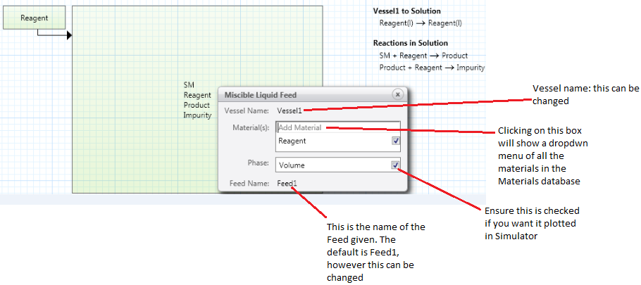
The top three parts of the window are for the Feed Vessel, and the last row is for the Feed Flow.
You can modify the Vessel Name or Feed Name by clicking on either and changing it. However, if the name contains a space or any of the following characters ¬`¦!"£$%^&*()-=+{}[];@’~#<>,.?,/ then those characters will be replaced by an underscore (_).
To add a material to this feed vessel, click on Add Material. This will bring up a dropdown menu where you can choose a component from the Materials section, or from the materials database or type in a new component name. To turn on plotting for any component, click on the check box at the right of its row.
You will see that the Volume of the Feed Vessel phase is automatically checked, meaning that it will be plotted in Simulator. You can uncheck this.
As you fill in the window, the following changes will be made to the model:
- Process Scheme section: The feed vessel and flow will be added to the process scheme picture and rate process text, with the associated materials.
- Materials section: For any new component, the name, formula and MW will be set. (Be sure to check the formula and MW in the Materials list.)
- Scenarios section: Columns will be added for the initial feed vessel volume (mL), the volumetric flowrate (Qv) of the feed (mL/min), and the initial amount of each material in the feed vessel (mmol).
A model can have more than one miscible liquid feed, if needed.
Dissolving Solid
Double clicking on Dissolving Solid in the toolbox brings you to the following window where we have already added Reagent to the list of materials:
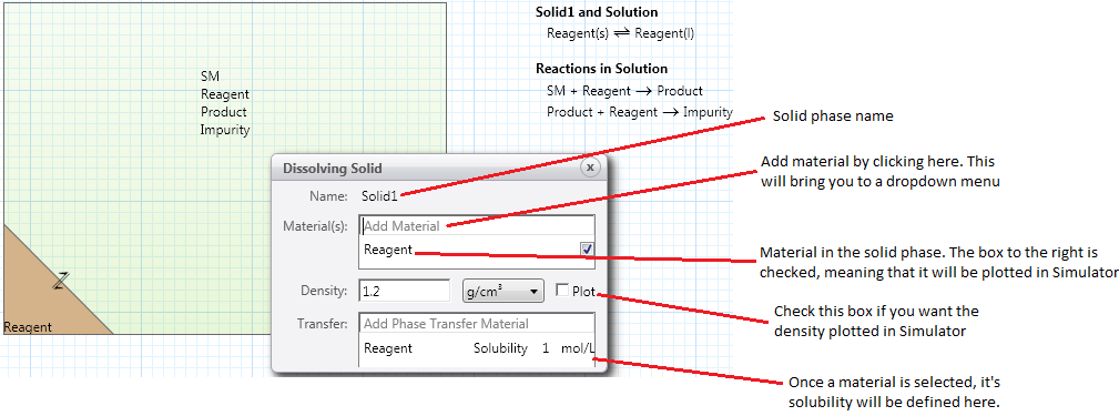
The top three parts of the window are for the Dissolving Solid, and the last part for the phase transfer of materials from the Dissolving Solid to the Solution.
If this is your first solid phase, the default name will be Solid1. You can modify the phase name by clicking on it and changing it. However, if the name contains a space or any of the following characters ¬`¦!"£$%^&*()-=+{}[];@’~#<>,.?,/ then those characters will be replaced by an underscore (_).
To add a material, click on Add Material. This will bring you to a dropdown menu where you can choose a component from the Materials section, from the materials database or type in a new component name. The same component will be added automatically to the materials transferred between the solid phase and the solution. To turn on plotting for any component, click on the check box at the right of its row.
The solid phase will be given a default density of 1.2 g/cm3. You can check the box to plot the density in Simulator. Each transferred component will be given a default solubility of 1 mol/L. To change the density and solubility values, click on any value and change it.
As you fill in the window, the following changes will be made to the model:
- Process Scheme section: The Dissolving Solid phase and phase transfer between the solid and the solution will be added to the process scheme picture and the rate process text, with the associated materials.
- Materials section: For any new component, the name, formula and MW will be set. (Be sure to check the formula and MW in the Materials list).
- Scenarios section: Columns will be added for the initial amount of each materials in the solid (mmol).
A model can have more than one dissolving solid, if needed. We recommend that each solid phase contain only a single component.
Precipitating Solid
Double clicking on the Precipitating Solid in the toolbox will bring up the following window, where we have already added Impurity to the list of materials:
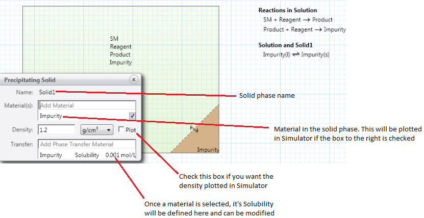
The top three parts of the window are for the Precipitating Solid, and the last part for the phase transfer of materials from the Solution to the Precipitating Solid.
If this is your first solid phase, the default name will be Solid1. You can modify the phase name by clicking on it and changing it. However, if the name contains a space or any of the following characters ¬`¦!"£$%^&*()-=+{}[];@’~#<>,.?,/ the those characters will be replaced by an underscore (_).
To add a material to this solid phase, click on Add Material. This will bring up a dropdown menu where you can choose a component from the Materials section, or from the materials database or type in a new component name. The same component will be added automatically to the materials transferred between the solid phase and the solution. To turn on plotting for any component, click on the check box at the right of its row.
The solid phase will be given a default density of 1.2 g/cm3. You can check the box to plot the density in Simulator. Each transferred component will be given a default solubility of 0.001 mol/L. To change the density and solubility values, click on any value and change it.
As you fill in the window, the following changes will be made to the model:
- Process Scheme section: The precipitating Solid section phase and the phase transfer between the solid and solution will be added to the process scheme picture and rate processes text, with the associated materials.
- Materials section: For any new component, the name, formula and MW will be set. (Be sure to check the formula and MW in the Materials list.)
- Scenarios section: No columns will be added. It is assumed that none of this solid is in the vessel at the start of the reaction.
A model can have more than one precipitating solid, if needed. We recommend that each solid phase contain only a single component.
Immiscible Liquid Feed
Double clicking on Immiscible Liquid Feed in the toolbox will bring up the following window, where we have already added Toluene and Reagent to the list of materials:
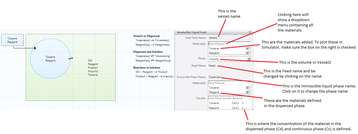
The top three parts of the window are for the Feed Tank, the middle row is for the Feed Flow, and the bottom part is for the Immiscible (Dispersed) Phase in the main vessel.
If an immiscible liquid phase is already present in the reactor vessel, this will connect the feed to that phase, otherwise it will create one.
You can modify the Feed Tank Name, Feed Name or Immiscible Phase Name by clicking on any of these and changing it. However, if the name contains a space any of the following characters ¬`¦!"£$%^&*()-=+{}[];@’~#<>,.?,/ it will be replaced by an underscore (_). To add a material to this Feed Tank, click on Add Material in the top section. This will bring up a dropdown menu where you can choose a component from the Materials section, or from the materials database or type in a new component name. The same component will be added automatically to the immiscible liquid in the reaction vessel, and to the materials transferred between the immiscible phase and the solution. Note that you can add materials to the immiscible liquid independently, if they are not present in the feed tank and are transferred between the immiscible liquid and the solution. To turn on plotting for any component in either phase, click on the check box at the right of its row.
You will see that the Volume of the Feed Tank phase is automatically checked, meaning that it will be plotted in Simulator. You can uncheck this.
The Transfer box at the bottom is used to define the materials that transfer between the immiscible phase and the solution, and their partition coefficients (Cd/Cc), with default values of 1–. Click on any value to change it. The partition coefficients show how the components distribute between the dispersed immiscible liquid and continuous solution phases. Cd denotes the concentration in the dispersed phase, and Cc the concentration in the continuous phase. For example, if the equilibrium concentrations of a material are equal in the two phases, its Cd/Cc is equal to 1. If a material is preferentially soluble in the dispersed phase, its Cd/Cc is greater than 1, e.g. 10 or 100. This parameter is unitless because the concentration units cancel out (mol/L)/(mol/L).
As you fill in the window, the following changes will be made to the model:
- Process Scheme section: The Feed Tank, flow to the Immiscible phase and the phase transfer between the immiscible phase and the solution will be added to the process scheme picture and rate process text, with the associated materials. If the Immiscible phase is not present already in the reaction vessel, it will be added to the picture. If needed, the components in the Solution phase will be updated in the picture.
- Materials section: For any new component, the name, formula and MW will be set. (Be sure to check the formula and MW in the Materials list.)
- Scenarios section: Columns will be added for the initial feed tank volume (mL), the volumetric flowrate (Qv) of the feed (mL/min), the initial amount of each material in the feed tank (mmol) and the initial volume of the dispersed phase (mL).
A model can have only one immiscible liquid phase (a total of two liquid phases) and one feed into it. This phase is treated as the dispersed phase for mass transfer calculations.
Immiscible Liquid
Double clicking on the Immiscible Liquid in the toolbox will bring up the following window, where we have already added Toluene and Reagent to the list of materials:
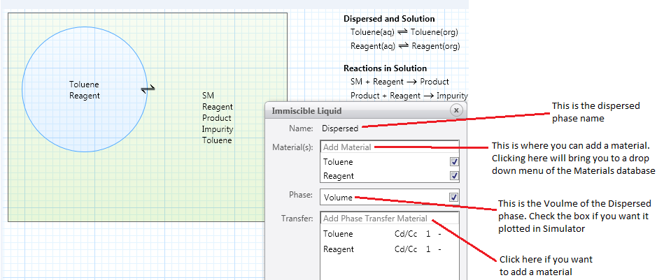
The top three parts of the window are for the Immiscible Liquid, and the last part for the phase transfer of materials between the Dispersed liquid and the Solution.
The default phase name is Dispersed. You can modify this name by clicking on it and changing it. However, if the name contains a space or any of the following characters ¬`¦!"£$%^&*()-=+{}[];@’~#<>,.?,/ then those characters will be replaced by an underscore (_).
To add a material to this immiscible liquid phase, click on Add Material. This will bring up a dropdown menu where you can choose a component from the Materials section, or from the materials database or type in a new component name. The same component will be added automatically to the materials transferred between the immiscible phase and the solution. To turn on plotting for any component, click on the check box at the right of its row.
You will see that the Volume of the phase is automatically checked, meaning that it will be plotted in Simulator. You can uncheck this.
The Transfer box at the bottom is used to define the materials that transfer between immiscible phase and the solution, and their partition coefficients (Cd/Cc), with default values of 1–. Click on any value to change it. The partition coefficients show how the components distribute between the dispersed immiscible liquid and continuous solution phases (Cd for concentration in dispersed phase, and Cc for concentration in continuous phase). For example, if the equilibrium concentrations of a material are equal in the two phases, its Cd/Cc is equal to 1. If a material is preferentially soluble in the dispersed phase, its Cd/Cc is greater than 1, e.g. 10 or 100. This parameter is unitless because the concentration units cancel out (mol/L)/(mol/L).
As you fill in the window, the following changes will be made to the model:
- Process Scheme section: The Immiscible phase and the phase transfer between the immiscible phase and the solution will be added to the process scheme picture and rate process text, with the associated materials.
- Materials section: For any new component, the name, formula and MW will be set. (Be sure to check the formula and MW in the Materials list.)
- Scenarios section: Columns will be added for the initial dispersed phase volume (mL) in the reactor.
A model can have only one immiscible liquid phase (a total of two liquid phases). This phase is treated as the dispersed phase for mass transfer calculations.
Gas Phase (Headspace)
Double clicking on the Gas Phase in the toolbox will bring up the following window, where we have already added H2 to the list of materials:
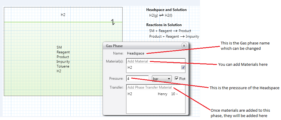
The top three parts of the window are for the Gas phase, and the last part for the phase transfer of materials between the Gas phase and the Solution.
The default phase name is Headspace. You can modify this name by clicking on it and changing it. However, if the name contains a space or any of the following characters ¬`¦!"£$%^&*()-=+{}[];@’~#<>,.?,/ then those characters will be replaced by an underscore (_).
To add a material to this gas, click on Add Material. This will bring up a dropdown menu where you can choose a component from the Materials section, or from the materials database or type in a new component name. The same component will be added automatically to the materials transferred between the gas and the solution. To turn on plotting for any component, click on the check box at the right of its row.
The gas phase will be given a default pressure of 4 bar and plotted in Simulator by default. You can click either of these and change it.
The Transfer box at the bottom is used to define the materials that transfer between immiscible phase and the solution, and their Henry constants, with a default value of 10–. The Henry constants show the solubility of each component in the solution (equilibrium concentration in the gas divided by the concentration in the liquid). The lower the value, the greater the solubility of dissolved gas in the solution. This parameter is unitless because the concentration units cancel out (mol/L)/(mol/L).
As you fill in the window, the following changes will be made to the model:
- Process Scheme section: The gas phase and phase transfer between the gas and the solution will be added to the process scheme picture and rate process text, with the associated materials.
- Materials section: For any new component, the name, formula and MW will be set. (Be sure to check the formula and MW in the Materials list.)
- Scenarios section: Columns will be added for the headspace pressure (bar), and the initial amount of each material in the gas (mmol).
A model can have only one gas phase. This phase is treated as the dispersed phase for mass transfer calculations.
Designating which liquid is aqueous and organic
For systems with two liquid phases, you can designate which liquid is labeled aqueous (aq) in the phase transfer text and which is labeled organic (org). In the process scheme picture, the aqueous phase is shown in blue and the organic phase in green.
By default, the Solution phase is designated as the organic phase. If you wish to designate this phase as the aqueous phase, double click on the Solution phase and choose Is Aqueous at the bottom of the dialog. This will switch the (aq) and (org) labels in the rate process text, and change the phase color to blue in the picture.
Note that this designation is independent of the phase names.
Removing a phase from the Process Scheme
To remove a phase, and its associated flows and rate processes, you can click on the phase to select it, then right click and choose Delete Selected Items. You cannot delete the main Solution phase.
The corresponding columns are also deleted from the Scenarios section.
User defined Calculations
To add user-defined variables and calculations to your model, first click on the f(x) icon  on the right side of the process scheme panel (The * is present if some user-defined calculations are already defined.) The following window will appear:
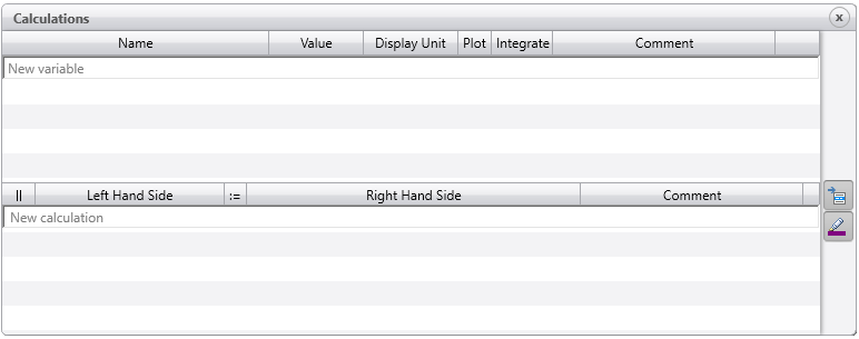
This window is divided into two sections. User-defined variables are defined in the upper section and the corresponding "calculate statements" or formulas are in the lower section.
In the Variables section, you type your variable name (e.g. Yield, Conversion, Uptake) in the Name column and press enter.
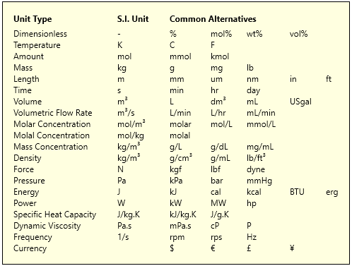
Once a variable is added, you can assign an initial value to it in the Value column and a unit in the Display unit column. If you hover over the Display Unit column you will see the following tooltip. This shows the S.I. Units and Common Alternatives for different unit types. You may use any of these units for input and output. Internally, all calculations will be carried out in SI units.
The plot column will be automatically checked, meaning that the new variable will be plotted in Simulator. Check the Integrate column if you will also calculate the rate of change of this variable in the calculations section (e.g. uptake.dydt). The Comments column can be used to write notes / explanations about the variable.
When adding a calculate statement (or formula) in the calculate section, first start typing the variable name at the left hand side. Reaction Lab will prompt you as you type to provide automatic guidance on variables and mathematical operators you can use. Examples are shown below:
1. How to input a Yield calculation
Note that the yield is calculated on a molar basis, not a mass basis.
2. How to calculate the Uptake of H2
If you have added a calculate statement that you no longer need in your model but want to keep it as a reference, check the box at the left of the variable name in the || column. This will grey out the calculate statement, therefore it won't be used in your model.
As in the variables section, the Comments column is left for any additional notes/explanation about the calculation.
There are different variables you may want to add to your model. To help out, we have listed the most common variables below.
List of built-in variables you can use in calculate statements
| Phase |
Component |
Definition |
| Solution. |
Component |
Moles of the component in the solution phase |
|
Component.mass |
Mass of the component in the solution phase |
|
Component.molFrac |
Mol fraction of the component in the solution phase |
|
Component.massFrac |
Mass fraction of the component in the solution phase |
|
Component.conc |
Concentration of the component in the solution phase |
|
Volume |
Volume of the solution phase |
|
Temperature |
Temperature of the solution phase |
|
Pressure |
Pressure of the solution phase |
|
Density |
Density of the solution phase |
|
Nmoles |
Number of moles in the solution phase |
|
Mass |
Mass of the solution phase |
| Dispersed. |
Component |
Moles of the component in the dispersed phase |
|
Component.mass |
Mass of the component in the dispersed phase |
|
Component.molFrac |
Mol fraction of the component in the dispersed phase |
|
Component.massFrac |
Mass fraction of the component in the dispersed phase |
|
Component.conc |
Concentration of the component in the dispersed phase |
|
Volume |
Volume of the dispersed phase |
|
Temperature |
Temperature of the dispersed phase |
|
Pressure |
Pressure of the dispersed phase |
|
Density |
Density of the dispersed phase |
|
Nmoles |
Number of moles in the dispersed phase |
|
Mass |
Mass of the dispersed phase |
|
kLac |
Mass transfer rate from the dispersed phase to the solution phase |
| Feed. |
Qv |
Volumetric flowrate from the feed tank into the main vessel |
| Headspace. |
Component |
Moles of the component in the headspace |
|
Component.mass |
Mass of the component in the headspace |
|
Component.molFrac |
Mol fraction of the component in the headspace |
|
Component.massFrac |
Mass fraction of the component in the headspace |
|
Component.conc |
Concentration of the component in the headspace |
|
Volume |
Volume of the headspace |
|
Temperature |
Temperature of the headspace |
|
Pressure |
Pressure of the headspace |
|
Nmoles |
Number of moles in the headspace |
|
Mass |
Mass of the headspace |
|
kLac |
Mass transfer rate from the headspace to the solution phase |
| Solid. |
Component |
Moles of the component in the solid phase |
|
Component.mass |
Mass of the component in the solid phase |
|
Component.molFrac |
Mol fraction of the component in the solid phase |
|
Component.massFrac |
Mass fraction of the component in the solid phase |
|
Component.conc |
Concentration of the component in the solid phase |
|
Volume |
Volume of the solid phase |
|
Temperature |
Temperature of the solid phase |
|
Density |
Density of the solid phase |
|
Nmoles |
Number of moles in the solid phase |
|
Mass |
Mass of the solid phase |
|
kLa |
Mass transfer rate from the solid phase to the solution phase |
| Reactions |
|
|
|
| Phase name. |
rxn1. |
k> |
Forward rate constant at Tref for reaction 1 |
| Phase name. |
rxn1. |
k< |
Backward rate constant at Tref for reaction 1 |
| Phase name. |
rxn1. |
Keq |
Equilibrium constant for reaction 1 |
| Phase name. |
rxn1. |
Ea> |
Activation energy for the forward reaction for reaction 1 |
| Phase name. |
rxn1. |
Ea< |
Activation energy for the backward reaction for reaction 1 |
| Phase name. |
rxn1. |
Component.stoich> |
Component stoichiometry in the forward direction |
| Phase name. |
rxn1. |
Component.stoich< |
Component stoichiometry in the backward direction (reaction must be reversible) |
| Phase name. |
rxn1. |
Component.order> |
Component order in the forward direction |
| Phase name. |
rxn1. |
Component.order< |
Component order in the backward direction (reaction must be reversible) |
| Mass transfer between two phases |
|
|
|
| LLE. |
Component. |
CdCc |
|
| GLE. |
Component. |
Henry |
Henry constant |
| SLE. |
Component. |
Solubility |
Solubility of the component |
| GLE. or LLE. or SLE. |
Component. |
Rate |
Rate of mass transfer in mol/s |
| GLE. or LLE. or SLE. |
Component. |
Kcda |
Overall mass transfer coefficient times specific interfacial area |
| Dispersed. |
Component. |
Cci |
Interface concentration (continuous) |
| Dispersed. |
Component. |
Cdi |
Interface concentration (dispersed) |
Solver Properties
To change the Solver Properties, click on the icon  on the right side of the panel. This will bring you to the window shown below:

Here, you can change three settings.
Firstly, you can modify the number of points you plot in Simulator.
Secondly, you can change the Integration Method. The options are Rosenbrock, Backwards-Euler and LSODA. The default method, Rosenbrock, is suitable for most applications. If you are working with a liquid-liquid model, the default is then Backwards Euler.
Thirdly, you can set the Accuracy of numerical integration to any value from 1.00E-02 to 1.00E-08.
Show/Hide rate processes as text
If you want to show the rate processes as text to the right of the Process Scheme, click on  . This will show all the rate processes in your model (chemical reactions and transfer between phases) and change the button to a dark background
  . Click on this again to hide the rate processes.